As marvellous an invention as the aneroid barometer was, it had many shortcomings, most of which were approached by various instrument makers over the 100 years or so of production.
Resolution, perhaps expressed as the reading to the highest number of decimal places, was an illusive goal. The problem relates to the expansion and contraction of the cell over a given pressure range: for example the cell may extend by as little as 0.013” when responding to a rise in pressure from 28” – 31” of mercury. The aneroid barometer is essentially a mechanical amplifier comprising a series of levers. A lever may either amplify displacement or force, one always at the expense of the other – nothing is for free!
So if we want to translate the extension of the capsule, 0.013”, onto a dial, we might have to amplify that original signal 800 times, and here we find ourselves wrestling with how to achieve greater resolution.
This might be approached by having a very large dial, not very user friendly if portability is a factor, and in addition the inherent mass of the pointer will only increase friction at the arbor.
Another solution is to dramatically increase the gearing or, put another way, cause the pointer to move a greater distance for the same input. The problem here is the loss in torque and the inevitable result that static friction, an ever present factor, becomes a greater restraint in both accuracy and response.
The mechanical solutions that might be looked at are quite a few, for example one could increase the length of the primary lever, that’s the extension from the bridge back to the spindle via a drop link. However, the instrument would have to become considerably larger to make this worthwhile and, of course, the result, though a greater deflection for the same input at the pointer, would be an associated loss of torque.
The partnership of Major Henry S.S. Watkin and James J. Hicks approached this challenge by using a very fine spiral pulley at the arbor, and achieved moderate success.
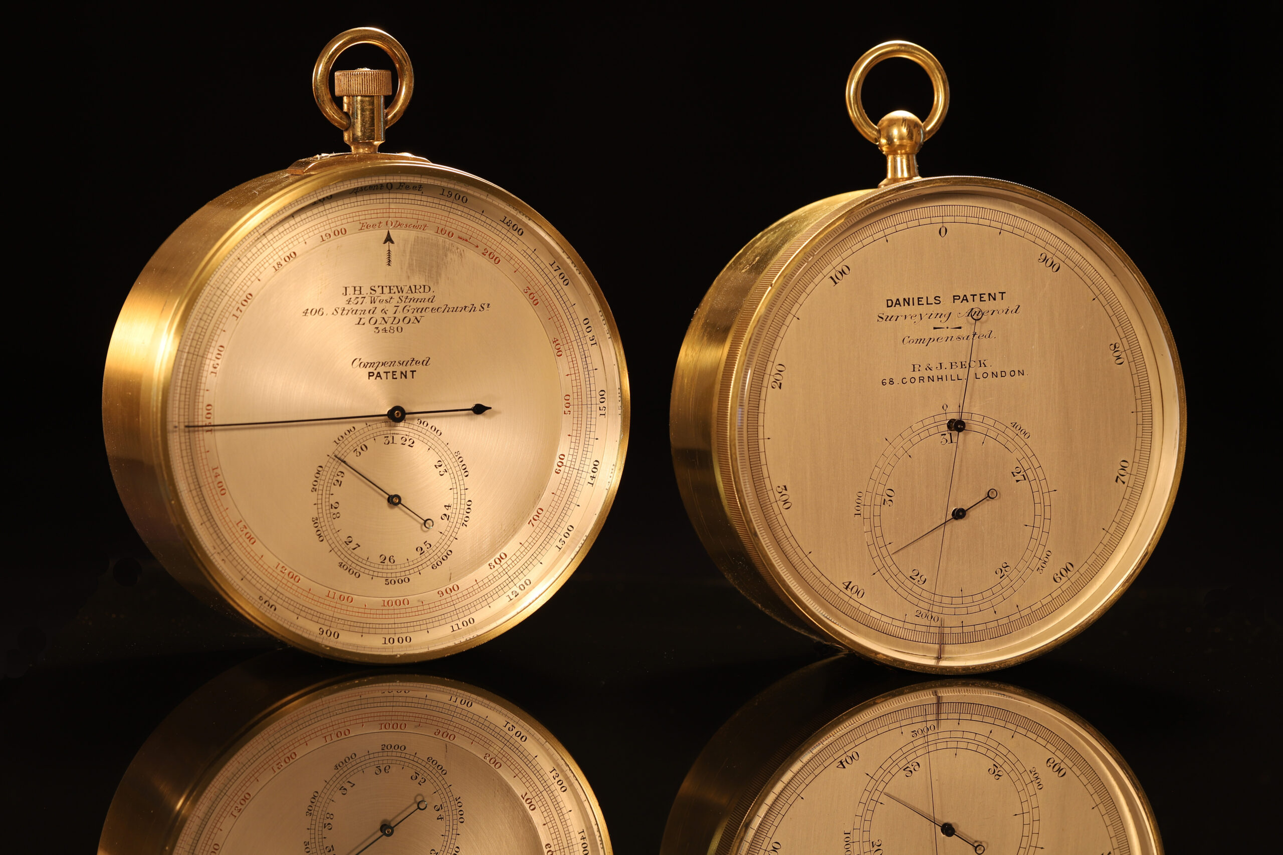
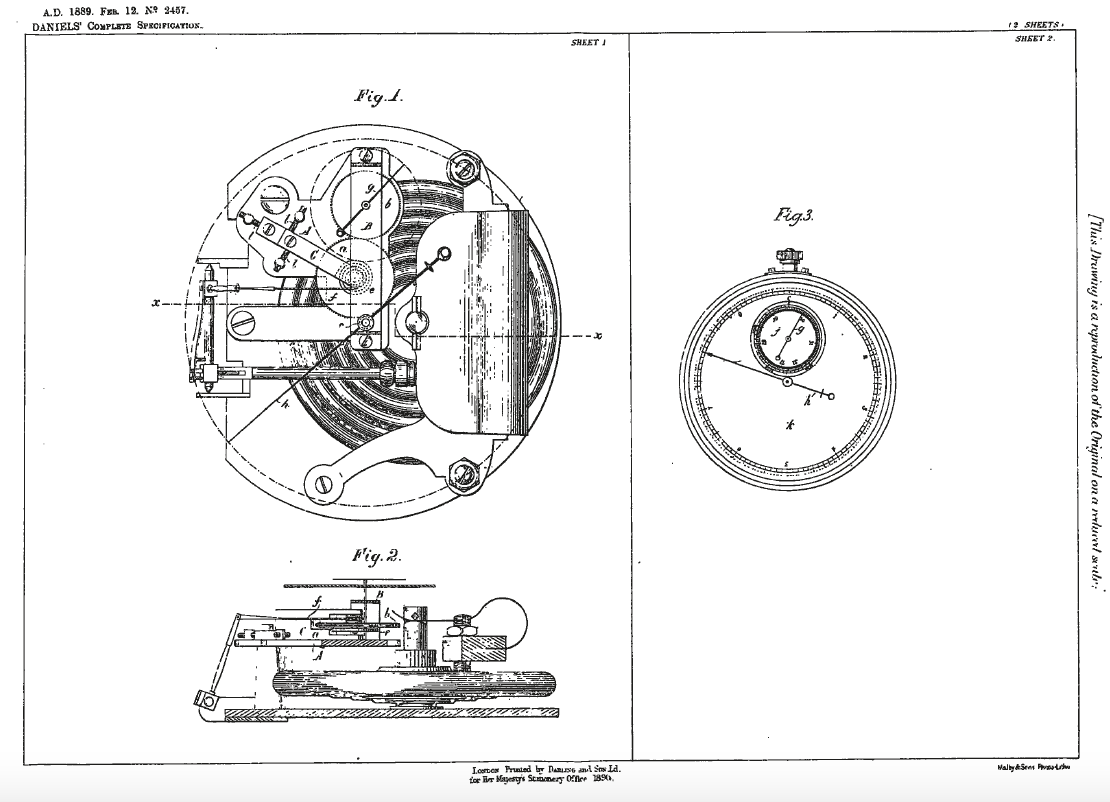
Perhaps the most elegant solution I have seen is found in the Daniels’ Patent No 2457, 1889, here demonstrated in two instruments – one made by the fine maker, JH Steward, the other retailed by, and possibly made by, R&J Beck, the Beck being the earlier instrument.
In both instruments shown, the bridge is very obviously the same, a likely arrangement resulting from the patent and the licence to manufacture being given by John Thomas Daniels to Steward and Beck. Execution of the engineering is quite different in both, suggesting very strongly that they were created by different makers.
Looking at the Patent, Daniels’ central claim is that: “This invention relates to improvements in aneroid barometers whereby the variations in atmospheric pressure may be rendered more readily apparent and indicated with greater accuracy than can be done by the ordinary single needle barometer, the movements of which usually extend over a fractional proportion of the dial.
My invention consists in employing two needles each travelling around a separate dial, one dial being graduated to indicate the inches or other units of pressure and the other graduated to indicate fractions or subdivisions thereof. To effect this I fix a toothed pinion to the upper end of the axis which usually carries the pointer at the same time connecting the chain and hair spring to this spindle in the usual manner.
Gearing with the pinion aforesaid are two smaller pinions one of which carries on its axis the pointer for indicating the inches or other units of pressure whilst to the axis of the other is fixed the pointer for indicating the subdivisions of the said units. The dials may be adjusted to zero by any suitable means. To diminish friction the edges of the larger pinion may be bevilled [sic] so as to reduce the amount of surface contact between the teeth of this pinion and those of the other two. The relative size of the pinions is arbitrary and may be varied according to circumstances.”
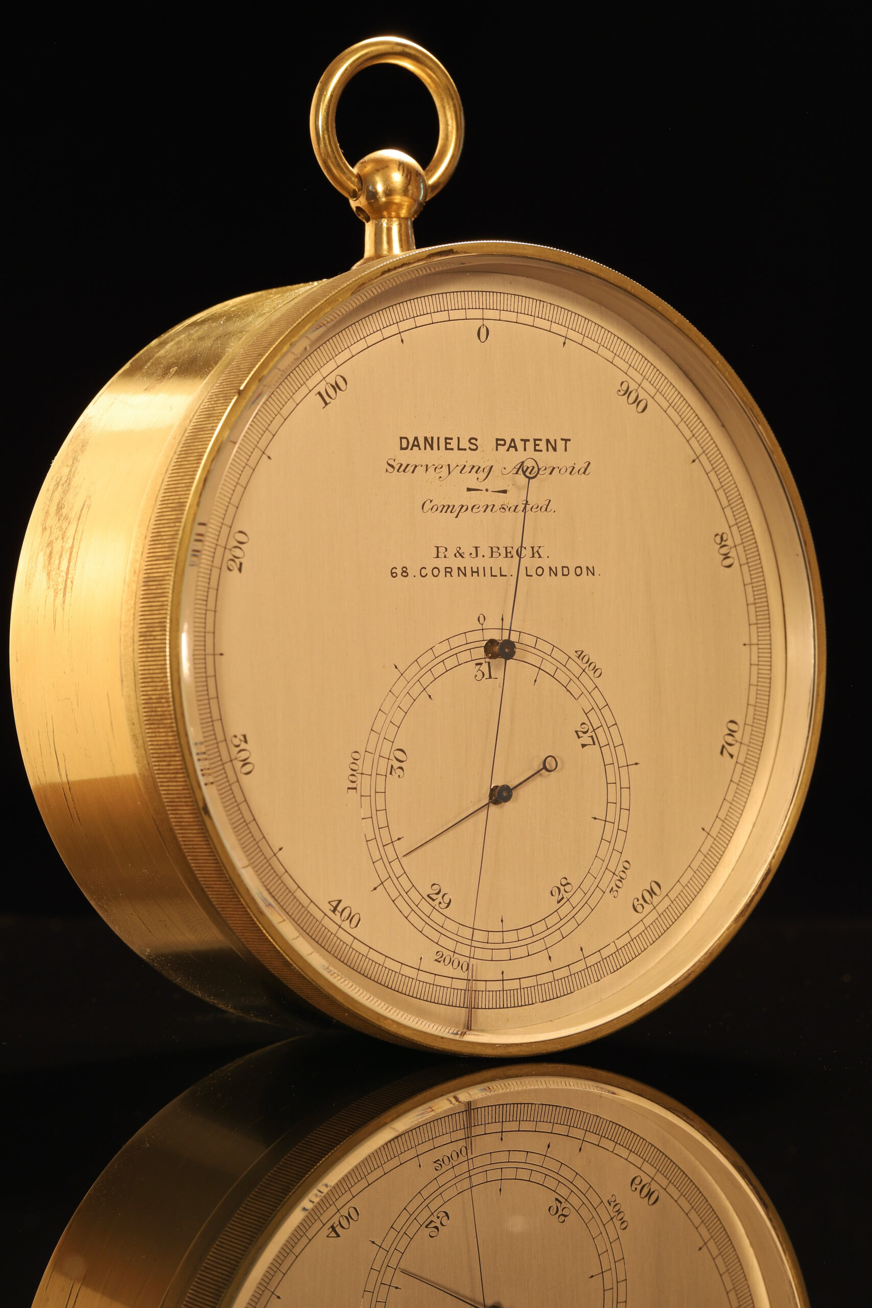
Let’s look at the dials first: both are actually very similar, with the open scale arranged at the outer edge of the dial calibrated in feet. On the Beck one rotation of the dial is 1,000ft, with the subsidiary dial (inset) having an outer scale marked in feet with a range from 0 – 4,000ft. This instrument is read from the subsidiary dial, the parts of this scale divided to 100ft, and the fractions of 100ft might then be read from the outer open scale. This means that the resolution is actually to one foot, or at least that is what the maker and inventor would like to imply. During various experiments I have been able to convince myself, probably, that this instrument does know the difference between sitting on my desk or being placed on the floor. The problem is that the indicated values are not consistent and can therefore not be relied upon.
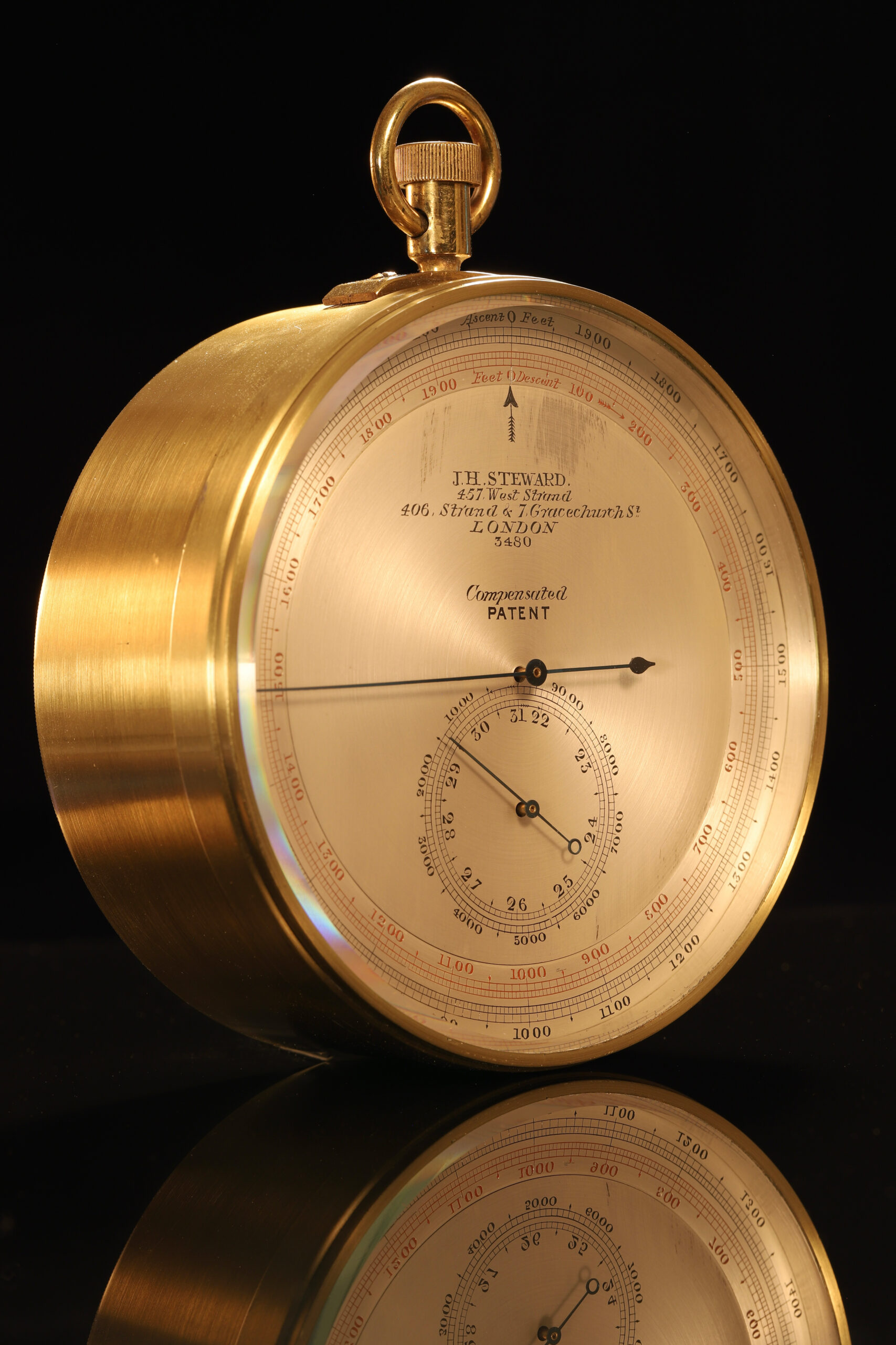
On the Steward example, the outer scale has a range from o – 2,000ft, and its subsidiary dial to 9,000ft, with resolution down to 5ft. The outer scale actually has two concurrent scales, one ascending and the other, reversed and in red, descending.
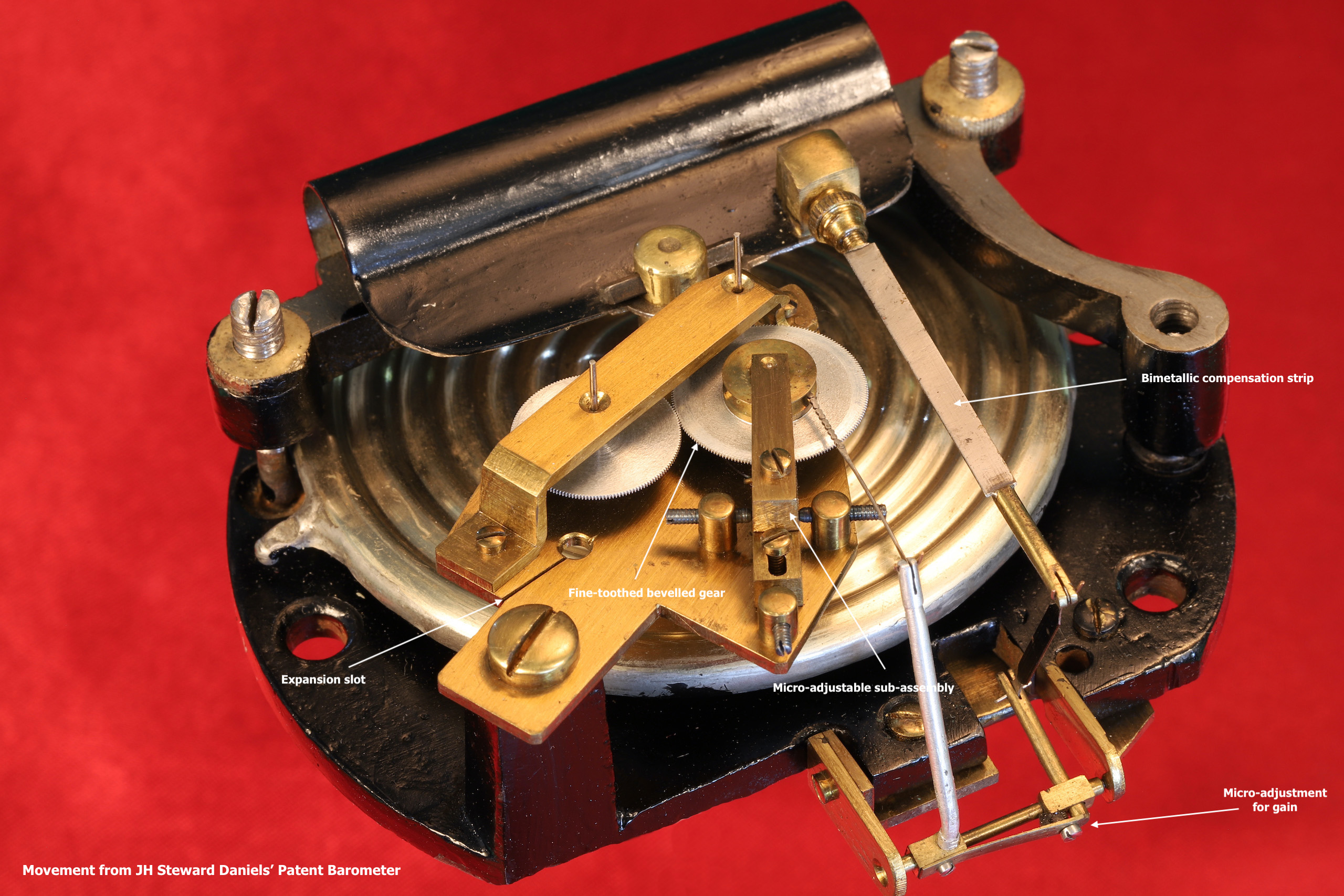
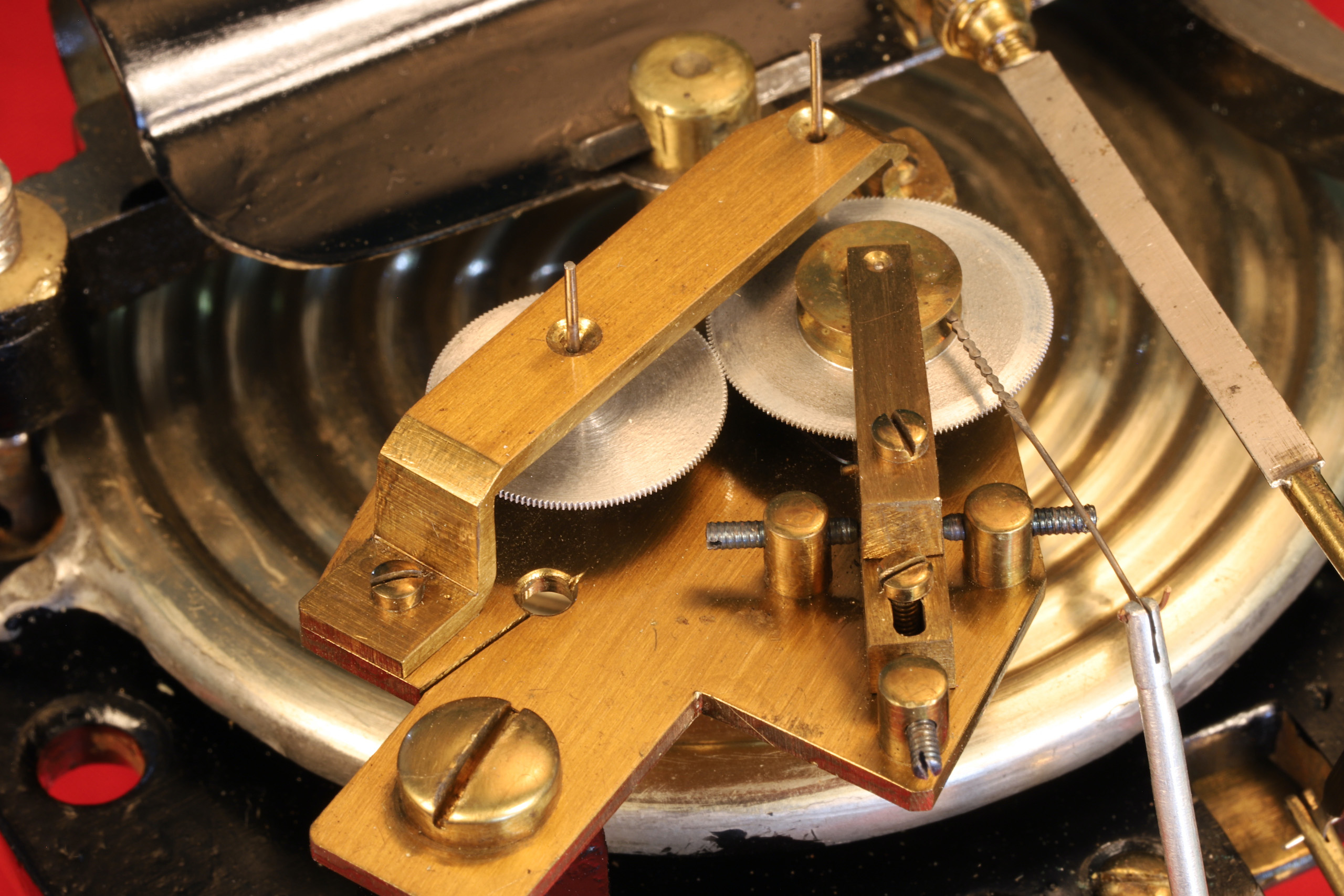
So to the engineering: in essence each is a standard aneroid barometer of the C spring pattern, having a single pressure sensing cell. To this a small gearbox has been added with a substantial base plate raised on a solid pillar or pillars, that of the Steward cut with an expansion slot, very sophisticated for the time. The primary gear is maintained in a sub-assembly with micro adjustment for depth and angle. The two gears are in fact about 0.010” thick, minimising friction at the teeth. This arrangement requires extremely precise engineering, near perfect alignment being essential, hence the sub-chassis with micro adjustment.
The gears are the obvious focus of attention. Other areas of unwanted friction resultant from the design principally found in the supporting arbors and pivots, the signal from the pressure sensing cell is transmitted to the primary gear via a fine chain, rotation is then distributed to the coarse scale or subsidiary dial, additionally calibrated in inches of mercury, as well as to the fine scale calibrated in feet, altitude.
These instruments certainly work well enough, though the implied degree of accuracy might not, in practice, be found. The added costs in engineering, and therefore the final cost to the customer, might have been significant, and in addition this is a far more delicate instrument and might perhaps fall out of arrangement more easily. These factors alone may explain why other less complex designs succeeded albeit with reduced resolution.
In any event, Daniels’ Patent is a significant development of the basic Vidi instrument.
Watch these Daniels’ Patent Surveying Aneroid Barometers in the laboratory vacuum chamber:
Beck Decreasing Pressure – Increasing Altitude
Beck Increasing Pressure – Decreasing Altitude