Fully functional operating model of a WWI Aeronautical Inspection Department (A.I.D.) works manufactured mechanical wing jig c1914-1918
A very important operating model of a works manufactured mechanical Wing Jig originating from the earliest days of airframe construction, probably manufactured by or for the Aeronautical Inspection Department (A.I.D.) during WWI
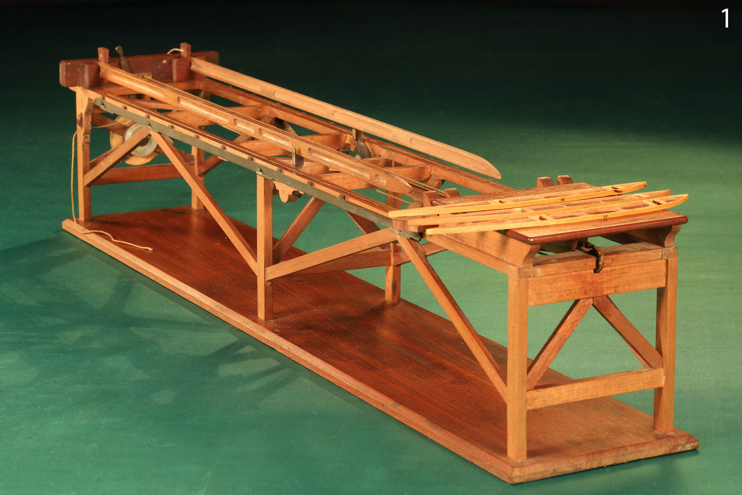
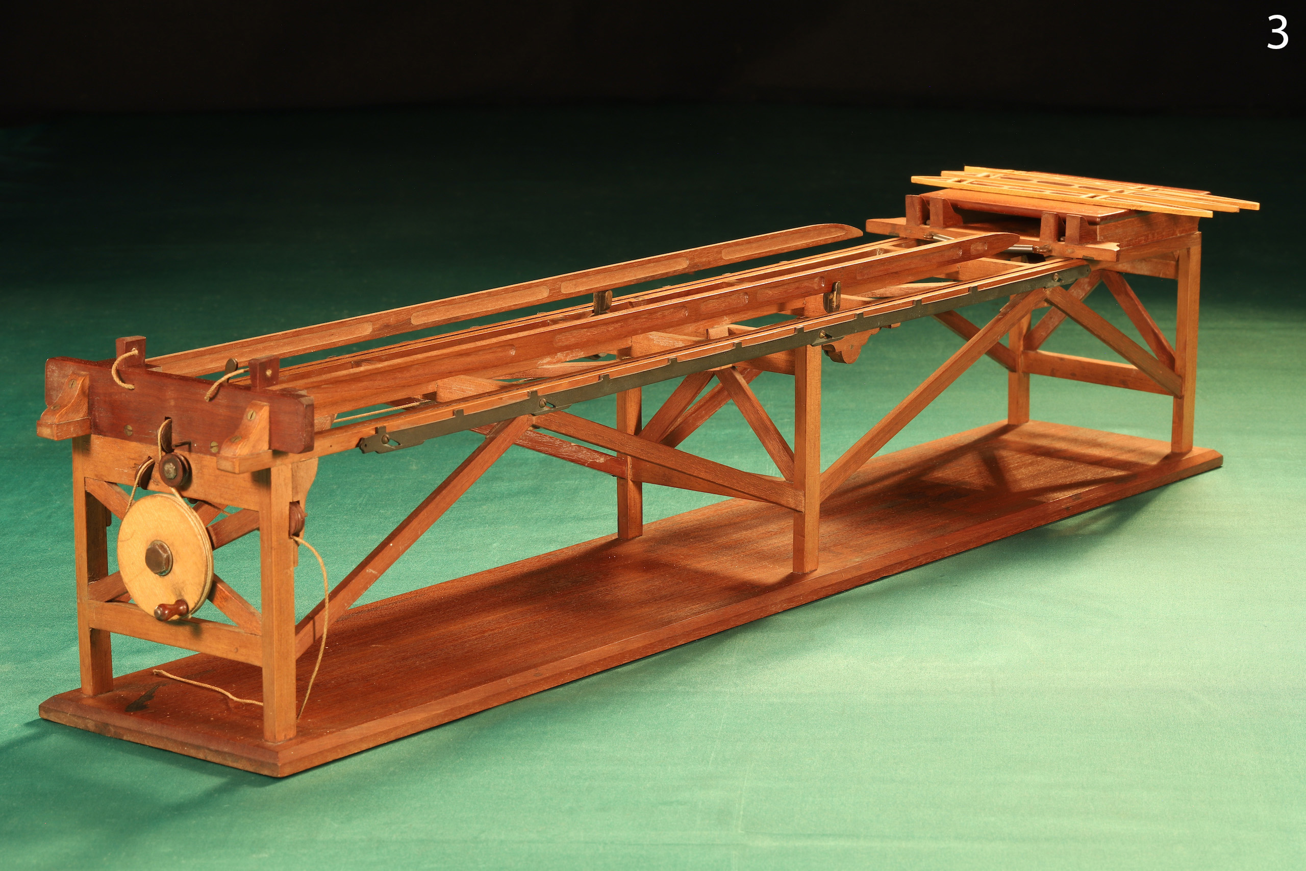
Constructed to the highest standards principally in mahogany with brass and steel fittings. The open triangulated frame structure supporting three parallel rails with grooved guides maintaining both the lateral and transverse stability of a sliding triangular form rib-setting shuttle drawn longitudinally by a cranked hand wheel connected by cords and spring tensioners and guided on pulleys. The outer rails set with twin spar-height maintaining cams rotating through 90 degrees on each shuttle pass. Lever-actuated side rail-mounted rising shuttle stops setting rib centres, main spars locking wedges, flat topped shuttle receiver and handling platform. The whole raised over bevelled full-length plinth.
Presented in its original pine transport case, remains of a label to the outer lid marked “Aviation Services.”
Operation: The two wing spars, front and rear, are located above the rails and situated in fixed positioning blocks secured with wedges, the further ends placed in associated guides on the shuttle upper surface, the spars supported at about the mid-point on rotating cams. Ribs are loaded in succession from the shuttle receiver onto the spar ends. The shuttle is then drawn with each rib along the rails to a predetermined point set by the rising shuttle stops. The rib, placed in the correct position along the spars and at precisely the right angle to the spars, 90 degrees, is now fixed permanently in position. The operation is repeated for each rib until the wing structure is complete. This method of construction determines precisely the rib centres and orientation ensuring a uniform and entirely predictable flying surface.
Condition: Generally exceptionally good, notwithstanding its age; nothing appears broken, the shuttle, rising stops and cams all articulate freely within the constraints of the design. One rising stop lacks part of the actuating mechanism. Wing ribs nos 2 and 3 are replicas modelled from no. 1.
Comments: This really is an extraordinary find – it surfaced completely untouched a while ago and it has taken me some time to actually get round to paying it the proper attention it deserves. The jig had possibly sat in its protective transit case, I would suggest, since at least the end of the Great War, I say that because it was covered in thick dust which over the years would have slowly permeated the box. Additionally, found within the box were two period photographs which time had caused to curl into a cylinder. Carefully straightening these with enhanced humidity, the images were clear, the jig itself with spars set and a number of ribs arranged along their length. As these images became apparent, very sadly so they slowly bleached out when exposed to daylight – it appears that after they were printed they were not fixed.
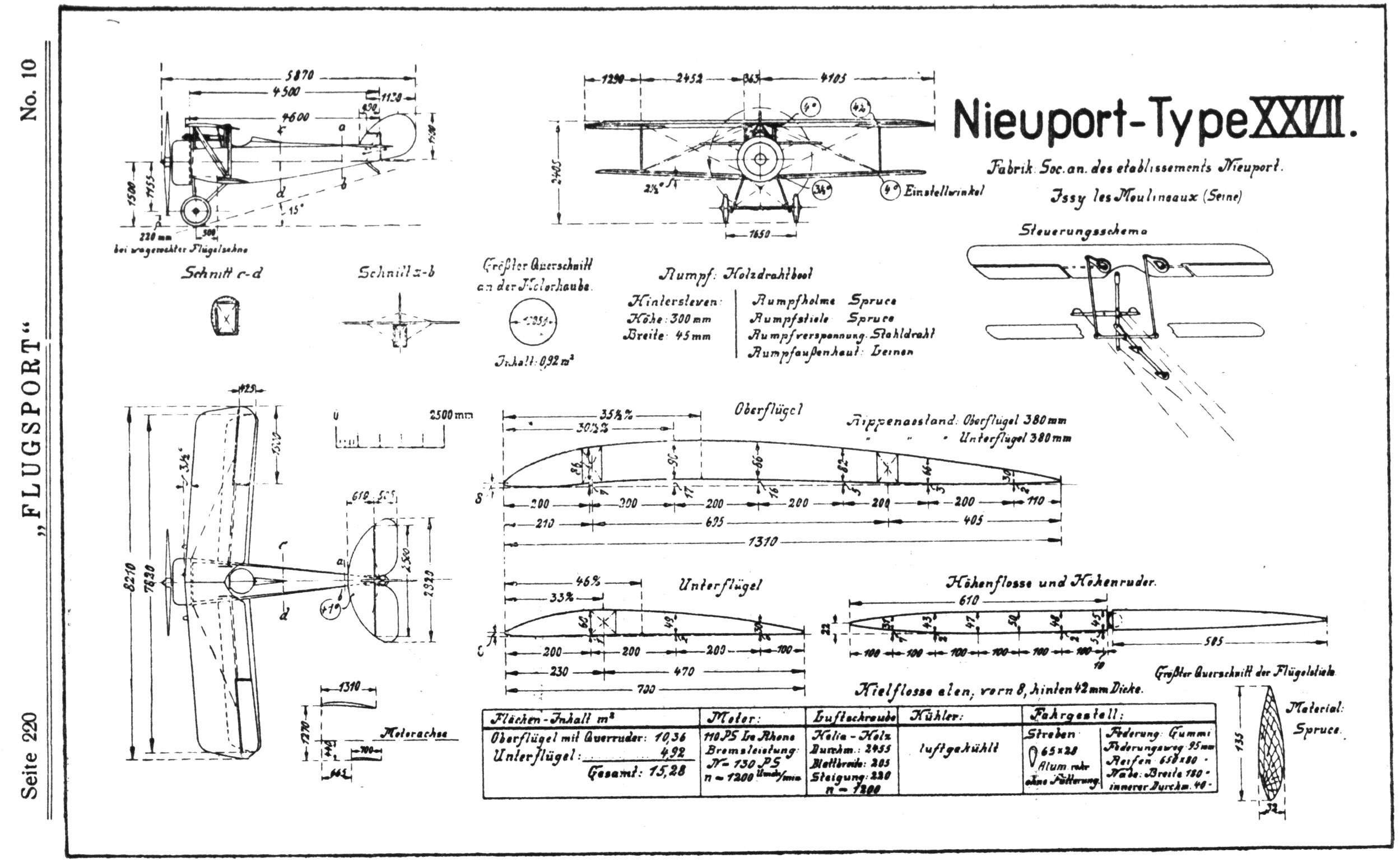
When I first became aware of what this item was, I contacted Shuttleworth Museum who said they had never seen anything like it and that the remaining original rib looked very much like that of a 1912 Blackburn Monoplane. Somewhere in the conversation a Nieuport Type XXVII was also mentioned. I include a schematic from a period publication, “Flugsport,” of this second aircraft, and the similarities in section are quite compelling. The original rib may not in fact have been a model of any specific wing section though looking at the subtleties of its form I would suggest that it was taken from a full scale drawing.
The construction of this jig is a lesson in the skills of model making more commonly found in the better dockyard ship models and works models of the later 19th and earlier 20th centuries.
However one looks at this, it is a very significant commentary on the evolution of early aircraft construction, a subject which, owing to its now very outmoded procedures, is widely overlooked and seldom investigated.
Association with the A.I.D., is of great interest. A government department created in December 1913 as a response to the many accidents with monoplanes in particular, air frame failure and the requirement to dramatically improve construction, design and materials, the scope of the A.I.D rapidly expanded, taking responsibility for almost every aspect of aviation including operation, supplies, safety, and so on. Precisely aligned with the ethos and responsibility of the Department this jig might have been constructed for or by their own craftsman to a design intended to improve the integrity and consistency of air frame construction.
Dimensions: X" wide x X" deep x X" high
Stock No: SI2226
Price: Vavasseur Archive - not currently for sale
Full schedule of images with descriptions below the photograph gallery
Schedule of Images
1 – 4 Oblique views, general arrangement, showing spars located, ribs positioned on loading platform prior to fitting, operating system with cables, pulleys and winding assembly.
5 – 6 Side elevations, general arrangement showing triangulated structure, positioning shuttle in shipped position below loading platform.
7 – 8 Oblique views showing one rib in position located on the spars, another in transport ahead of the shuttle, and another on the loading platform.
9 – 10 Elevated view of loading end, shuttle in contact with rib for positioning, shuttle standing off from rib showing general form.
11 – 12 Elevated views showing a rib positioned for transport along the spars by the shuttle, three ribs in position.
14 – 15 Elevated longitudinal views showing positioned ribs, spars and general arrangement.
16 – 17 Elevated views, ribs in position, annotations, spar labelled “AID 86M” and “ “Rear” Top,” the identity of “86M” is unknown but may refer to an airframe type or assembly number.
18 – 19 Close ups, shuttle, and shuttle with rib, note attention to detail, the shuttle drawing cable being correctly spliced, and shuttle transport cord tensioning springs.
20 – 21 Close ups, spacing rack castellations, extended as a shuttle stop and retracted to allow shuttle progress along guide rails.
22 – 23 Close ups, as the shuttle passes along the guide rails the spars are supported on cams at approximately the centre point of the spars, the cams of right angle form and pivoting at their apices allow the shuttle to pass, maintaining support to the spar.
24 – 25 Close ups, general views of operating system. Image 24, top right is a lever that may be moved transversely left and right causing the spacing rack to extend or retract, the rack is spring tensioned to its retracted position, tension on the connecting cord causing it to rise to its engaged position locking the shuttle and so the rib to pre-determined centre.
26 Close up of original rib and two facsimiles, the original marked “AID 86M.”
27 – 29 Elevational views of ribs and a comparison to a period drawing of Nieuport XXVII rib, the similarities are compelling.
30 – 31 The original pine transport box with remnants of a label affixed to the lid, the words “Aviation Services” are just legible to the bottom.
32 – 33 Original photographs of the Wing Jig with spars and ribs showing. These photographs are severely bleached and badly cracked, and they substantially corroborate the age of this model Wing Jig.